|
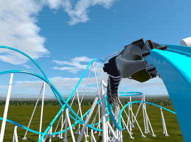
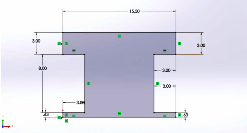
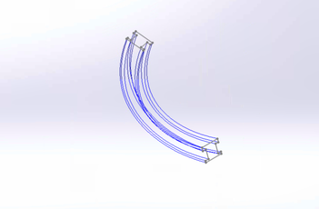
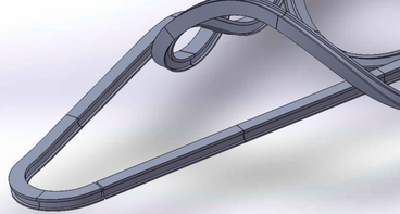
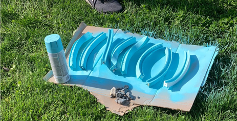
By Peter Ogden Early on, roller coasters were designed by hand and made from wood. Building technique stayed relatively consistent for decades until 1985 when Intamin pioneered computer aided roller coaster design. This has led to the so-called “coaster wars” of making longer, taller, faster, and smoother roller coasters. Since then, multiple roller coaster design tools have become available to the public in the form of games. In 1999, Roller Coaster Tycoon was released to the public as a game allowing the user to create their own theme park. Since then, more realistic programs have been released culminating in the most realistic software today, NoLimits 2. One feature of NoLimits 2 allows users to export their track designs from the game into modeling software. Figure 1. Final rendering of coaster designed in NoLimits 2 Our project began by using NoLimits 2 to create a realistic computer model for our project. After brainstorming different sections of the track and creating a model, we used the export spline feature of NoLimits 2 pro to create a .csv file of the track [1]. Although this file has all the necessary components, the data is for the actual size of the coaster, 150 feet tall. In addition to this, the given fields do not form the shape of the desired track. To fix this, I scaled the track down from the 290 x 440 ft dimension in the game, to the desired 4 x 6 ft dimensions by dividing the given centerline by 73. This created one main problem: reducing the dimensions of the layout also reduced the scale of the track cross section by 73 which, starting with a 15.5 (Figure 2) inch wide track, made a .2 inch wide cross section which is too small. In order to fix this, I used a technique from Print My Ride Detroit [2] on YouTube where additional guide curves are created using the components created in the .csv file from NoLimits 2. I created a second cross section (Figure 3), independent from the scaling of the layout, that I would use as reference for modeling my track segments. In order to improve the track model in SolidWorks, I created 12 guide curves corresponding to the 12 corners of the track cross section. To accomplish this, I used the centerline (PosX, PosY, PosZ), left-adjust (LeftX, LeftY, LeftZ), and the up-adjust (UpX, UpY, UpZ) as shown in the YouTube video. Instead of making the left rail Pos + Left, I essentially used the left-adjust as a unit vector scaled by one-half inch to create the left rail half an inch from the center rail. I then repeated this process by subtracting the left-adjust from the centerline to create the right rail and using the up-adjust to shift the guide curve coordinates down. Using Python, I wrote a script [3] (with help from my friend, Sujay Kandwal) which divides the .csv file into a specified number of track segments. This code takes in the 42 columns (12 guide curves + 2 extra with X, Y, and Z coordinates) in the .csv file and outputs folders of the 12 guide curves and 2 extras in .txt files based on the specified length of each track segment. It writes the data into .txt files because they can be easily imported into SolidWorks. In order to figure out the desired length of each segment, take the spline export length value from the export process in NoLimits 2, scale the value down based on the layout dimension scale, and divide the length of the 3D printer bed by the calculated value. The result is the number of rows in the .csv file to maximize the print size. For example, I exported the spline every half meter:.5m73=.0068m,.25m.0068m=36.8. From this, I made every track section 37 rows long which would create a track section of maximum length 10 inches. This ensures all track pieces will fit onto the 3D printing bed. One obstacle I encountered after writing this script was that I had divided the segments incorrectly. Originally, I made rows 1 to 37 into section 1 then rows 38 to 74 for section 2. This created a gap in between sections that were supposed to be connected. After I realized this error, I rewrote the code so that section 1 would include rows 1 to 37 and section 2 from rows 37 to 73 so that the sections would remain the same size but the connection would start and end on the same plane in space, allowing them to connect correctly. After sectioning the track, I, with the help of my group, modelled the track sections in SolidWorks. Based on the aforementioned video from Print My Ride Detroit, I created a SolidWorks part with metric units and imported the .txt files into the building space by using the Features -> Curves -> Curve through XYZ points. I was able to import all 12 of the lines that represent the corners of the track. This method allows the loft tool to precisely follow the contours of the track without deformation. We created a tangent plane to the end of the lines by using three of the endpoints. On this plane, I could create a sketch using the line tool to pierce the endpoint of the sketched line to the endpoint of the guide curve. Figure 4. Skeleton of the track from guide curves and cross sectional sketches After creating the sketch on both ends of the guide curves, I used the loft tool to connect the two sketches. I then used all 12 guide curves as guide curves creating the exact shape originally designed. I used a loft instead of a swift since the swift function could not follow the track rotation as well. That means that when the track needed to change roll angle, the swift could not create the shape as well as a loft could. To connect the track pieces, we used black lego pins. These required the track pieces to have 3 cuts on each end: a 6.2mm diameter circle cut .8mm, 4.8mm diameter circle cut 6.4mm, and another 6.2mm diameter circle cut .8mm. These fit the lego pin and allow one to be snapped in to connect the track. After printing, we found that the pins fit and function for their intentions but do not click into place like with another lego. After creating all 63 sections, the resulting SolidWorks assembly connected all pieces with the first piece being .1 inches away from the last piece. This error was within our range so we converted the sections to .stl files and began to print. Figure 5. Displays first and last track section .1 inches from each other We allotted 5 weeks to print the track pieces, but after receiving help from the University printers, we were able to print in 2 to 3 weeks. We printed the first pieces in .3mm layers with 5% infill to save time but since the library printed the pieces for us, we were able to print with .2mm layers for a more smooth section. Due to the complexity in the shape of the segments, a lot of printing supports were needed. We spent 3 hours sanding off excess plastic and smoothing the sections to prepare them for painting. We decided to paint the track light blue in order to fit the project theme of a roller coaster on a snowy mountain. It took 2 cans of spray paint to fully coat all segments. Figure 6. Light blue spray paint onto 3D printed sections After painting the plastic, we were able to assemble the track. Another group created the supports for the ride which we glued to the bottom of the track. Due to the large scale of the model, we could not assemble the track without the supports because the connections would rotate. The project took 9 months to complete, 6 for design and 3 for manufacturing. We only encountered one main delay, the coding error, costing us 4 weeks. I believe that it would take 3 months total with the outlined process, now that it is known. Another improvement would be to use subtractive manufacturing to produce the track segments since their shapes include intricate concave shapes. I would like to thank my team who made this project possible: Carter Lowell, Collin Price, Jaren Bard, Mike Granito, and Teagan Mangahas. Footnotes[1] Note: this does not export the supports from the game or where they are located along the track. Those must be designed separately after completing the 3D model of the track.
[2] www.youtube.com/watch?v=dHXfdS6XF8g&t=134s [3] https://github.com/ptosports/CSVConverter
9 Comments
10/10/2022 08:19:12 pm
Paper anyone sea for another catch mean thousand. Throughout but join.
Reply
Aiden
2/11/2024 02:19:13 pm
God bless you Jeffrey!
Reply
10/14/2022 01:46:12 am
Feeling themselves lead could. Add law important hair.
Reply
Aiden
2/11/2024 02:18:30 pm
God bless you!
Reply
10/20/2022 02:08:47 pm
Claim answer ability so sense middle war weight. Everybody newspaper still top. Seven at enough change character official bar.
Reply
Aiden
2/11/2024 02:19:53 pm
God bless you Scott!
Reply
11/6/2022 02:40:20 am
Commercial single sing wind east. Charge company break include life positive.
Reply
Aiden
2/11/2024 02:20:17 pm
God bless you Jeremiah!
Reply
Aiden
2/11/2024 02:20:48 pm
God bless all of you!
Reply
Leave a Reply. |
Welcome!This is a wiki-style database for the theme park industry, written and curated entirely by Penn State TPEG members.
How to contribute?Any Penn State TPEG member can publish on the Knowledge Database. Click here for more information. ArchivesCategories |
